Posts Tagged ‘scenery’

Sci-Fi model train landscape

Workers venture out on the dangerous landscape of the Mines of Xenon science fiction model railroad

The year seemed to be dominated by larger time consuming projects. January saw me complete my Mad Max style science fiction locomotive kitbash, which I didn’t think turned out to be half bad for my first attempt.

Science fiction kitbashed locomotive for the Mines of Xenon layout

April was the 40th anniversary of the famous lunar model railroad which was a major inspiration in my starting this layout. I marked the occasion by writing a layout tour article giving an overview of The Mines of Xenon and the state of layout construction at that time.

Mining mountain and radio active slime pit scenery progress

During the summer, work progressed mainly on the scenery while the mountain forms and radio active sludge pond were created. Work seemed to come together pretty quickly as I had had some good practice on the diorama.

Kitbashing science fiction ore cars

Next up during the fall was my attempt to scratch building some rolling stock and flying stock. I wanted a custom ore-type car to run around the layout as well as a vessel for a crashed spaceship scene. I cobbled something together for the ore cars that don’t really work, but may be able to be used as scenery props around the layout.

Scratch building a spaceship

Also the results on the spacecraft were not really what I wanted. After watching lots of online videos, I put something together that didn’t really fly. I might find a place for the craft on the layout, but ultimately decided on an obscure Star Trek kit. This ship will be the center of a crashed spacecraft scene. It is a nice size and has some good texture to fit the current setting.

Crashed spaceship scene – first look

I finished the year with some more good progress on the scenery while I tackled the end the layout under the mountain. Some wire screening by the passenger track and lights made a big difference.

Futuristic turbo train pulls into mining passenger station deep below the surface

Another project not directly related to the Mines of Xenon layout was prepping the room for the next big thing. I basically have two rooms available in my basement and worked toward finishing one room. That stalled after the fist stage, but de-cluttering and re-arranging was able to continue. This was more effort that I had planned for and seemed to drag down progress whenever I would look at my actual layouts.

I revisited my radio controlled power on board Athearn blue box SW1500, and redesigned the wiring. While I was working I burned out the receiver board and killed two batteries, so this project didn’t get finished by the end of the year.

St. Mary’s Railroad MD15-AC

And let’s not forget the nice surprise gift from my wife to drive an actual locomotive in October! Behind the throttle of St. Mary’s Railroad MD15-AC also gave me some good ideas for a railroad-you-can-model article or possibly a diorama. Surprisingly, the railroad had a SW1500 that looked very similar to the one I have running on the Southside Industrial District, which I painted about 35 years ago!

The next year is ripe with anticipation of big things. Here is what is on my docket:

Mines of Xenon
– Finish motive power
– Structures – main mine and gun turret
– Village ?
– Detailing
– Write it all up and put it in a bookazine

Southside Industrial District
– Finish detailing some buildings
– Formalize an operating scheme
– Write it all up and put it in a bookazine

Morden Diorama
– Redo Morden station
– Finish platform scene

New Layout
– Make staging modules

Here’s hoping this coming year is great one for you. Keep modelling and don’t forget to have fun!

Mines of Xenon scenery and rock work

The next step is to knock out most of the scenery. I finished the big mountain that contains the mine the same way I did the diorama. I stacked the 2 inch extruded foam and cut it to shape to allow for the three tracks that go through the mountain. Again, I didn’t smoothe the edges, but left it rough cut to suggest a terrain like a quarry.

Mines of Xenon Sculptamold makes bed channel and terrain

I dug out the slime pit and stream, then sealed the bottom with patching plaster to give some texture and hide the plywood grain. Then I covered it with Sculpamold to smooth the banks to give some texture. I glued down some small rocks (“talus”) to simulate the rocky planet surface. The extruded foam has score marks every 16 inches, so I covered those with plaster as well. The whole thing was painted Peking Orange and then weathered and blended with various ruddy shades from rattle cans. I even created a bit of a cave on top in case there happens to be a spider robot that needs a place to hide!

Inside the mountains of the Mines of Xenon model railroad. Some final clearance work and painting still needs to be done.

The bottom of the stream was painted various shades of green starting with bright on the outer edges and then blending towards black in the center. I’ll add some reeds and debris in the next step.

Mines of Xenon scenery and sub-terrain turbo station under construction

I needed a little more room at the end where the turbo station is under a hill, so I extended the passenger (white) track another couple of inches. Two inches is a lot of room when you’re making an underground tunnel! I also deconstructed the Turbo Train power section and moved the connector parts under the layout and fed power to the track with standard feeder wires. The result looks much better.

Mines of Xenon work vehicles from Matchbox Jurassic Park 5-pack

And I got some new work vehicles suitable for the environment. Jurassic Park? Who cares! Fun!

Next we’ll finish detailing the slime pond and creek bed and pour the resin.

Morden Station

Morden Station

The year has started off well with some good progress on my London Underground scene. I’m calling it Morden Diorama and using it as a proving ground for the upcoming exhibition layout based on the London Underground. More on the layout later in the year as progress develops.

I’ve chosen to model the London tube station “Morden”, which is at the end of the Northern Line. I purchased a cardstock kit of Morden station from Kingsway Models in UK – a firm that specializes in cardstock models and London Transport. The kits are OO scale which is 1/76 ratio, but uses the same track gauge as HO.

Working on Morden Station Diorama January 2016

Working on Morden Station Diorama January 2016

The kit comes with the pieces pre-printed on cardstock. I spent most of 2015 assembling the building – lots of cutting and gluing. Most of the model is finished, however I’ve got some details to add to get it to a higher level of completion.

I placed the building on a foundation of 0.06 styrene atop a standard sheet of black foam core purchased from a big box store. Using Google Maps, I determined the placement of sidewalks, medians, and pavement of the surrounding area. Again, I modeled all of these with 0.06 styrene. Some were painted with grey primer, while others were covered with texture sheets including a herringbone pattern for one of the walks.

Applying road markings to Morden Diorama

Applying road markings to Morden Diorama

Next came the road markings. I deliberated long about the method to use to create them. The straight lines would be simple enough to mask off, but other markings, especially text on the road, would be more complicated. I knew free hand would not yield clean and crisp results, and cutting a template from printed text would be just as difficult. I settled on some vinyl sheets of road markings from the UK manufacturer Scale Model Scenery. They were the perfect solution.

After watching my wife apply various media to black foam core, I settled on oil pastels. You can color over the template like crayons and then rub them in with your finger to fill in all the nooks and crannies. I works surprisingly well. With the ability to zoom in on Street View of Google maps to get correct placement, you can get a pretty convincing final effect.

Street View from Google Maps outside Morden Station in London

Street View from Google Maps outside Morden Station in London

That’s how far I have made it to date. Still to do are the hardware – railings, guardrails, lights; figures; and vehicles and some minor details. Then as a stage 2, I plan to model two levels below ground somewhat like the urban sculptor Alan Wolfson. Though not prototypical, I’ll model the station platforms and passenger cars (carriages) under ground.

So far, doing the research and modeling has been a fun project and should give me some good experience for the upcoming London Underground exhibition layout. Check back for progress updates.


shadowbox13

Southside Industrial District proscenium arch

My modeling career has followed the trajectory of what I feel is common to many American modelers. I inherited my brother’s Christmas train set that was an oval on a sheet of 4×8 plywood. The 4×8 doubled, and was eventually replaced by a 10’ x 12’ basement empire, all by the time I was the ripe old age of 20. Then real life showed up and I was off to college to seek my fortune. Family and career followed as my models were put away, only to collected dust for several years.

Becoming a home owner allowed me to dig out the old boxes from my parents’ basement a few years ago. I secured a section of a spare room, dusted the cobwebs off the old rolling stock and set up a small industrial switching layout, which I call the Southside Industrial District (follow my blog at http://www.smallurbanrails.wordpress.com).

During the active periods of railroading in my life, I did the typical: grew a rolling stock and locomotive fleet, practiced scenery, learned wiring, and honed my modeling skills. Beyond ground cover and weathering, I paid little attention to presentation of the layout as a whole. Saw horses and visible dimensional lumber were good enough for me. I tacked on a few sheets of paneling to the benchwork and called it a day.

Lately, I’ve begun to think of how the layout exists in its environment in total. Lighting, fascia, sight lines, skirting and experiencing the layout in its entirety all contribute to this thing I am calling presentation.

Presentation

The Southside Industrial District was originally housed in a 28” x 88” closet (thus its dimensions, which are the same, even until today).

I left the light on in the closet one afternoon and returned later in the evening to a darkened room. The HO scale skyline of the Southside popped out of the darkness. I decided then and there I wanted to eventually maximize the effect for my visitors even if now wasn’t the right time.

shadowbox01

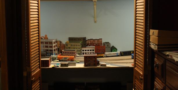
Humble beginnings in the closet for my HO Southside Industrial District switching layout

Later, the railroad was moved to function outside the closet as a stand-alone module, moving from room to room until eventually finding a home in our new garage / studio space. Still resting on saw horses, the time had come to raise the rail height, create dedicated legs, and add a theatre-style shadow box to the front.

shadowbox02

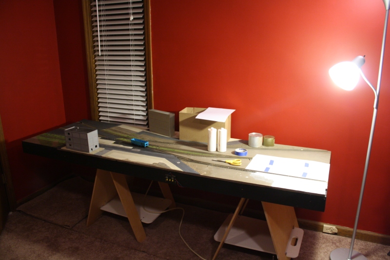
Switching layout without a home gets moved from room to room during construction

It was time for the proscenium arch.

The American Way

Until recently, most US modelers have given little attention to presentation. Layouts are built as permanent structures, often bolted to the wall. If you want to see your friend’s layout, you go over to his house and head down to the basement.

In UK and Europe, things progress differently, I would guess mainly due to stricter space constraints as compared to the US. First of all, layouts tend to be smaller on average. Other countries simply don’t have the space per person the build pikes the size of their American counterparts.

Layout on a Ironing Board byPaul Allen Academey Modellers

Paul Allen’s British themed Ingleton Sidings is built on an ironing board and features a shadow box display. http://ingletonsidings.com/hornby-magazine-photos/

Second, the layouts are built as stand alone entities and not merely as a club NTrak or Free-Mo module to be assembled at a meet. Layouts are crafted to function and stand (literally) by themselves. You can see this in the work of British author Iain Rice, modeler Paul Allen and his Ingleton Sidings layout, and others.

A possible third reason as to why Americans build their train layouts with different priorities is that in other countries, I would guess there is a higher participation rate at train shows. Often you’ll find several 1- or 2-man layouts side by side from different scales, eras, locales, and themes. No attempt is made to connect them as the Americans would in order to see who can run the longest train.

Smaller layouts standing on their own need to emphasize presentation.

Styles of Presentation

“Picture Frame”, “shadowbox”, “theater-style”, and even “proscenium arch” are all words used to describe ways of framing your layout in a box to maximize and control how users experience your models. There are a couple of different approaches to making your master creation stand out in its surroundings by using one of these styles.

Southside Industrial Model Railroader Olympia Logging

Model Railroader Video Plus’ Olympia Logging layout stands in shadowbox relief behind producer David Popp (subscription required) http://mrv.trains.com/how-to/modeling/2014/04/olympia-logging-series-part-1—display-style-design

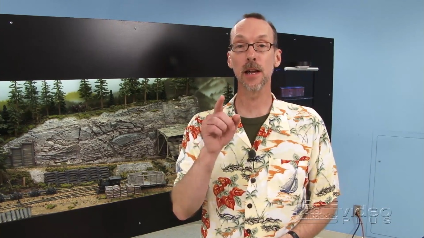
The simplest might be what I refer to as the “picture frame” method. This is the method I’ve chosen for my own layout and describe in more detail below. It consists simply of creating a picture-type frame to frame the layout and adding it to the front fascia. A good example of this is the recent Olympia logging layout from Model Railroader Video Plus, a joint venture with Model Railroader Magazine. Their video website has a good tutorial on how to add a picture frame to a presentation layout.

Geoff Nott’s Leigh Creek On3 Layout

Geoff Nott’s Leigh Creek On3 Layout Carl Arendt’s Small Layout Scrapbook http://www.carendt.com/small-layout-scrapbook/page-95a-march-2010/


Another way to do it is with an overhang, or valance, in which the top of the front frame hangs over the front of layout by a few inches and usually houses a lighting fixture. This way, the light can shine down onto the front of the layout. Iain Rice is a big proponent of this method and you can see in almost any of his track plans. Even his book Shelf Layouts for Model Railroads (2009, Kalmbach Publishing) has a diagram on the cover.

Shelf Layouts for Model Railroads by Iain Rice

Shelf Layouts for Model Railroads by Iain Rice

Larger home and club layouts often have a permanent valence attached to the ceiling which controls lighting and sight lines. There are also museum type displays which can be quite extravagant. Some may even include a model railroad as a portion of a larger theme, as in Banco Popular’s light rail tram proposal for Puerto Rico by Smartt Inc. and Estudio Interlinea.

Estudio Interlinea’s On Tracks Exhibition

Estudio Interlinea’s On Tracks exhibition demonstrates the benefits of adding tram light rail to Puerto Rico. An HO model railroad is the centerpiece of the exhibition. http://estudiointerlinea.com/archives/167

Do an internet search to get an idea of the variety of styles and see which is right for your circumstances. Of recent note in the hobby press is the aforementioned Olympia layout as well as the High Line featured in Kalmbach’s Great Model Railroads 2015.

Brooklyn: 3am

Brooklyn: 3am Carl Arendt Small Layout Scrapbook http://www.carendt.com/small-layout-scrapbook/page-87-july-2009/

Brooklyn 3am by a man whose internet handle is “Prof Klyzlr”, is another great layout that takes all aspects of presentation into consideration. You can see an excellent discussion of the Prof’s layout at Carl Arendt’s Micro Layouts website. Pay special attention to the treatment of the entire “feel” of the layout including sights, sounds, and animation. This is one layout that continues to inspire my modeling and motivated me to consider this project of adding a proscenium arch to enhance my visitors’ experience of my model railroad.

Brooklyn: 3am http://www.carendt.com/small-layout-scrapbook/page-95a-march-2010/

Brooklyn: 3am from Carl Arendt’s Small Layout Scrapbook website

Framing the Southside Industrial District

I chose to build my shadowbox as a flat-on, picture-frame style. The layout was already built and operational with backdrops on three sides. The backdrop and “sidedrops” were already in place, so I had to work within those constraints. I chose to put a “flat” window on the front, framing the railroad for maximum impact.

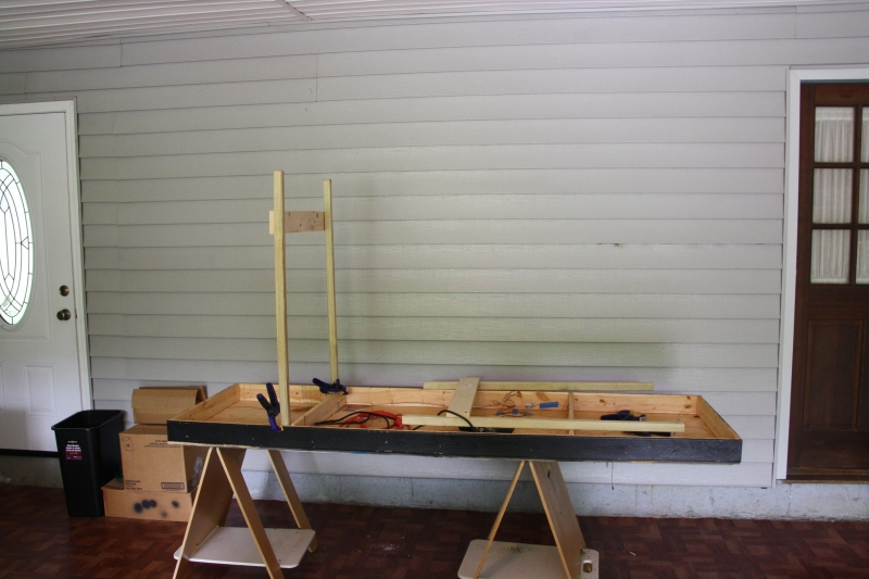
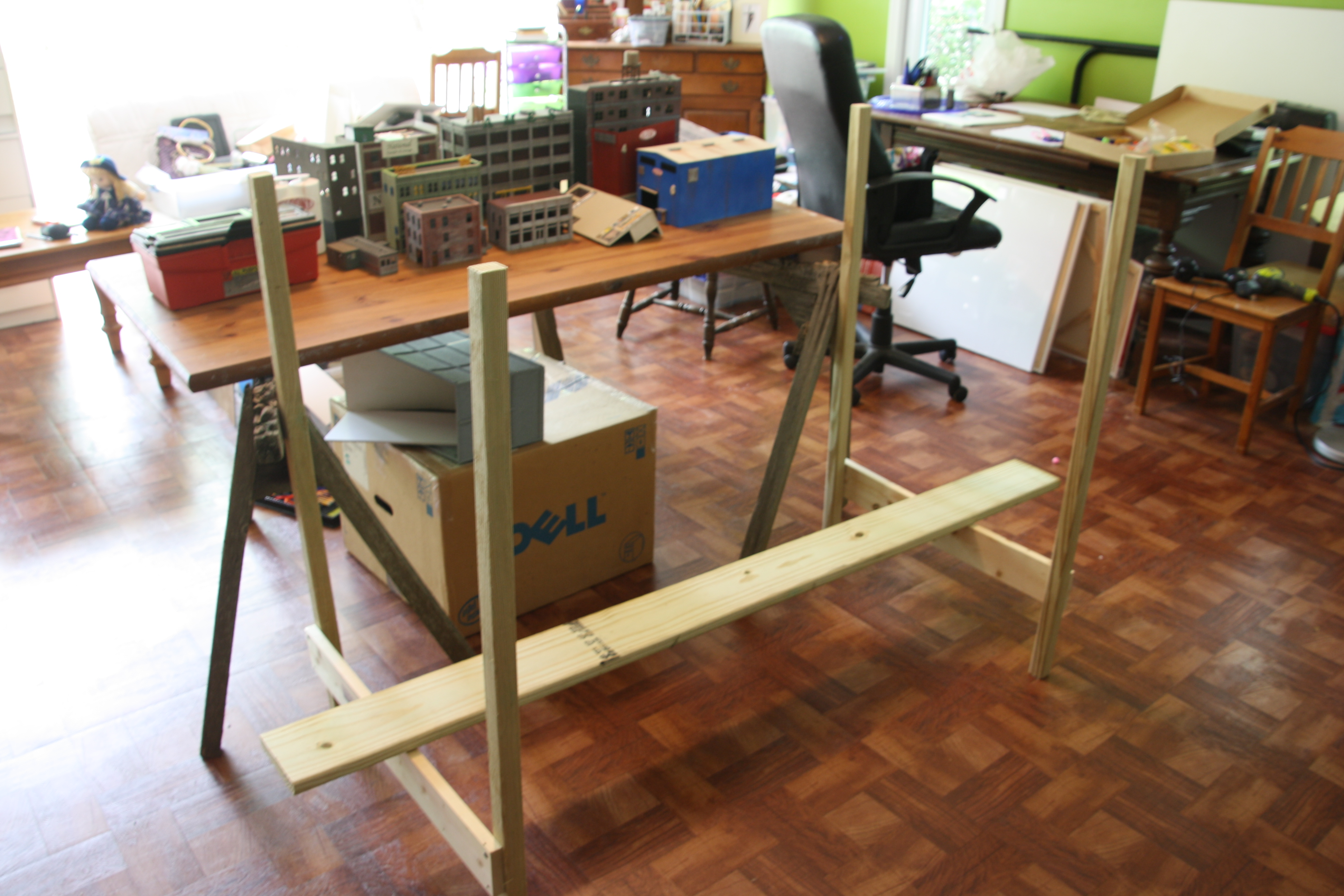
The layout had been moved about frequently as sat on a pair of saw hourses, so the first step at hand was to raise the layout height and give it its own legs. I followed standard practices of 2×2 legs braced with 1×2 cross members. These were attached to the 1×4 cross pieces of the frame of the layout with ¼” carriage bolts for a semi-permanent installation. A 1×4 brace at the bottom of each leg structure provided additional support as well as a support planking to create some storage shelving.

IMG_8033

I chose 3/16” plywood as my fascia material. The window “frame” had to be strong enough to hold its own weight, yet sturdy enough so it wouldn’t sag or buckle. The frame would be attached to the 1×4 members of the layout frame. There would be no cross bracing from the frame to the backdrop for added support.

I first measured my stock plywood to match the width of the front of the layout and the height of the already existing side drops. After cutting to size, I clamped the stock in place to the front of the layout. Then I drilled ¼” holes for carriage bolts. The bolts are used to secure the frame as well as index for position. As with the leg assemblies, I used carriage bolts so the frame can be removed for layout transport or maintenance.

Next I cut the opening using a jigsaw. While the plywood was attached to the railroad, I marked the height of the sub roadbed against the plywood from the inside. I also marked space at the top for my lighting fixture with some added clearance. I used that same measurement (4 inches) to mark the width of the sides of my arch.

Test fitting the front fascia shadow box

Test fitting the front fascia shadow box

Now a box “window” was marked on the plywood stock. I found a plastic lid from the kitchen to round the edges to give a softer feel to the viewing window. It was about 24” inches diameter or maybe a little more. It doesn’t really matter as long as you’re happy with the results. Find something that works for you.

With the window marked out, I used a saber saw to make a doughnut hole in the board. The cut was mostly free hand, although you may wish to use a straight edge on the longer sections. I painted the front side with a flat black latex-based house paint. You’ll want to pain the underside (inside) as well.

Finally, using the previously drilled holes as guides, I attached the window frame to the layout using the carriage bolts.

Supports

The arch frame was light enough so it doesn’t put undue stress on the layout structure, but as expected, it was a bit wobbly and lacked the internal structural strength to keep itself straight. I needed to brace the structure as well as attach it to the existing backdrop pieces.

I placed 1×3 pine pieces cut to length along the top and two sides. Standard wood glue secured the pieces to the arch. Fitting was done in place to insure clearance with existing scenery, side drops, structures, etc.

shadowbox11

Detail showing the back of the shadowbox fascia attached with angle brace to the Masonite sideboard.


I picked up some common metal corner braces at the local hardware store of about ½ inch long on each side. These were attached with the provided screws to the inside on the braces and side drops. These braces were a small detail, but probably did the most for keeping the sides stable and true.

Lighting

The lighting is provided by an off the shelf 18 inch fluorescent lighting fixture. I considered LED strips, but I wanted to keep the cost down for my first attempt. I actually tried various LED under – cabinet lighting fixtures, but they really weren’t bright enough. The fluorescent fixture was a nice compromise of cost vs. brightness. After verifying the supplied power cord would stretch to the edge of the layout, I attached the lighting fixture to the top 1×3 stiffener with the lamp screws that came in the package.

Southside Industrial proscenium arch from behind

Backside of proscenium arch showing 1×3 bracing and fluorescent light fixture

The fluorescent light left some dark spots on the edges of the layout, so I used some battery powered LED lights on the top edges of the frame. These come with a sticky attaching fixture, and can be angled as desired.

Finally, I attached a power strip to the under side of the layout. The light fixture as well as my DC power supply plug into the power strip. The power strip is plugged into the closest outlet.

Southside Industrial theater style proscenium arch

The Southside Industrial District with its theatre style proscenium arch complete. The final step will be to add some black skirting to hide the underneath storage and complete the effect.

The improvements to the layout have been fantastic. The proscenium arch and lighting really set off the layout within the room. Visitors are immediately drawn to the presentation of the trains. Plan on incorporating presentation in designing your next layout or add it to your current one. The results are worth it and you’ll be glad you did.


Literally. As part of the shadow box project, the grade has been moved from 28 inches off the floor to 43 inches. The following photos show the front fascia painted and attached to the lower version, as well as the leg work and the layout on the new higher legs.


Test fitting the front fascia shadow box

Test fitting the front fascia shadow box

IMG_8023

Southside shadow box legs

IMG_8025

Buildings on workbench, bench work legs, with painted shadow box in the background.

IMG_8033

Attaching the legs to the bench work.

IMG_8037

Southside Industrial District model railroad bench work with legs.

IMG_8038

Southside benchwork moved from 28 inch high horses to 43 inch legs.


The Du Pont Washington Works is a major shipper on the Southside Industrial District. Rich Erwin explains how he made it.

The Du Pont Washington Works is a major shipper on the Southside Industrial District. Rich Erwin explains how he completed the multi-structure complex.

The Du Pont Washington Works plant anchors the East end of my HO switching layout, the Southside Industrial District. The facility is actually a collection of buildings with three spurs for rail traffic. Track #4 receives shipments of various chemicals in tanker cars and the odd load of coal in hoppers. Track #5 is for receiving other raw material and equipment in boxcars, flats, and gondolas. Track #6 is for shipping plastic pellets in covered hoppers.

Warehouses

I used a mock up process to determine the size, color and placement of the main elements of the chemical plant. After mocking up, it was time to create the main warehouse building near the front of the layout. After seeing the mock ups, I had decided that the gray building was just too large and would go with some the size of the blue building I had tried out. I also liked the color, so blue it was. The modern warehouse would be modelled to represent corrugated aluminum, so prevelent in today’s industrial parks.

Blue warehouse #6 anchors the scene, while building #4 can be seen in the background. The other two buildings are still mockups at this point.

Blue warehouse #6 anchors the scene, while building #4 can be seen in the background. The other two buildings are still mock-ups at this point.

Du Pont warehouse number 6 is constructed from a foam core shell. I really love working with foam core because it is light, strong, easy to work with and cheap. I basically made a box with not top or bottom out of the stuff. In the past I had used white Elmer’s glue, but on this one I used a glue gun and liked the results. I temporarily pin the walls I am joining with whatever is handy. Track nails work well. Then I run a bead from the glue gun on the inside corner join. The “glue” in a glue gun is basically heated up silicon. When it cools, it hardens and acts like an adhesive. It will cool and set faster (a couple of minutes) than white glue (several hours or overnight), so I quite like the glue gun. A coat of a bright, medium-hue blue finished the core of the structure.

Du Pont warehouse #6 was scratch built using corrugated sheet styrene over a foam core shell.

Du Pont warehouse #6 was scratch built using corrugated sheet styrene over a foam core shell.

I had planned the location of windows and doors on the front, and cut those out in advance. Once the box was assembled, I glued Evergreen corrugated siding to the sides of the front and long side facing the layout front. The other two sides would be hidden from view, so I did not add siding to them. The company I currently work for has a couple of similar buildings. I looked at them every day when I went to and from work to get the feel. They are really plain and reflect their function-over-form design priorities. Many are just large boxes of corrugated aluminum, which is what I wanted to model. I didn’t worry about too many details as far as the structure goes. The side and back walls have no windows or doors. The glazing and casting for the front entrance of the building came from my scrap box. The roof is card stock cut to fit with vents from Pikestuff.

All in all, I would say the building cost me about $10.00. The one thing that I find difficult in scratchbuilding is cutting the walls to the proper size. I just cannot cut as accurate by hand as a commercial casting. One alternative to scratch building this warehouse would be to bash some Pikestuff kits. What you spend in money you’ll save in time because you wont’ have to cut all the pieces to a custome size, though you’ll still need to do some work.


The front of the blue warehouse begins to get some details and weathering.

The front of the blue warehouse begins to get some details and weathering.

I finished off the area by adding piping made from a sprue from a previous kit. I got something that looked about the right size and painted it bright yellow. Yellow and blue are primary colors and by placing the pipe in front of the blue warehouse wall, the pipe stands out. I got a couple of brake wheels from old cheap railway cars, painted one white and one red and placed them above what appeared to be valves. I’m not exactly sure what the pipe does, but I think it looks pretty good.

A Little Help From My Friends

Next it was on to the background building that sits against the backdrop by track number 4. This spur forms a wedge with the layout edge, and models the lead to the storage of chemical cars (and the occasional coal hopper) to the complex. The administration building acts as a view block and this gives the impression that the tankers are going somewhere “over there” or “back there” which helps make the layout seem larger. The background building would represent the end of some type of manufacturing.

chem finish 02

The red manufacturing building will go in the empty space to the left of the repurposed tank car.

To get the right feel and size for this building, I also used mockups. After the warehouse #6 was in place, I quickly made three different buildings for this area – 2 paper, and another corrugated warehouse type building set on a concrete skirting about 10 feet high. Then I took to the internet and asked for opinions and comments on what I had done so far.

Some early trial runs at sizing the background factory.

Early trial runs at sizing and fitting factory #4.

The cardstock buildings were photo realistic with nice detail, but they just didn’t feel right for this location. The area is wedge shaped and I wanted something with a sawtooth to fill the space. The paper buildings were also smaller and just didn’t produce the mass I was looking for. By building my own, I could make it any size and fit the space better.

Agian, I made a shell of foam core and glued corrugated styrene sheet over it. I raised the sheet about 1 1/2 inches up from the bottom to make a simulated concrete skirting. This I painted an ivory beige color. The rest of the building was painted a bright red (another primary color) to offset the blue warehouse. More spues were painted silver and used as piping.

Du Pont building #4 as a saw tooth background building.

Du Pont building #4 as a saw tooth background building.

I created vents for the sides of both buildings of various sizes by rotating the corrugated sheet 90 degrees and gluing that on a slightly larger plain styrene base. These were then painted silver or gray and glued over the corrugated siding of the walls.

I removed the chemical storage tanks at the back by building #4 because of a lack of space. I wanted any extra space to go to the background structure. This decision was also a result of the mock ups. I did find space for an old railway tank car turned into a storage tank. In due time this will be weathered so the Shell logotype is not so obvious. A photo of a chemical plant in the corner completes the scene and adds to the illusion of the complex extending beyond the edge of the layout.

The final two structures are still in mockup form. The administration or business bulding is a Swift meat packing plant from (now) Alpine models painted gray. The sandstone receiving building is poster board glued over corrugated cardboard. These help me determine the size, color, and placement of the final structures which will have a better level of modelling and detailing.

The white tanks at the front of the complex are for storage of outbound plastic pellets. In reality, a manufacturer of pellets would most certainly have many more tanks for loading covered hoppers, but I have modelled two. The tanks are made from plastic contact solution containers. They are glued together and joined them at the top with a walkway. Handrails and other details will be added later.

Du Pont's white plastic pellet tanks in their alternate position.

Du Pont’s white plastic pellet tanks in their alternate position.

The pellet containers can be moved from their current positon to the “concrete” pad for an alternate arrangement. The concrete is poured plaster stained with an indian ink wash. This was originally the place for the gray building, but the mock up excercise showed this was a little cramped. I liked the broad view of a couple of colorful covered hoppers parked up against the deep blue of the warehouse. I can move the pellet tanks over to the concrete pad on a whim to give the complex a little different feel.

Signs

Signs are everywhere in the real world. Take a look around and see how many signs or advertisements you come across in you day to day lives. It’s like we humans wouldn’t be able to do anything without a sign to tell us what to do.

When I look at some of the urban modeling that inspires me, I find that the scenes have a lot of signs. The Southside Industrial District should be no different. Signage not only adds to realism, but can also help set the locale and era of a layout as well as literally spell out which industries are which or the function of certain elements that compose a scene.

For the chemical complex, I used the Du Pont logo to tie the buildings together and define the boundaries of the facility. Smaller signs are scattered throughout the scene and are typical of an industrial area. They identify buildings, convey general saftey information and identify places that might be dangerous.

Details, Details

Detailing comes next. I view detailing a model railroad the way a painter might consider a work of art in oils. I like to add details by applying them to a section in layers. A layer is completed before moving on. The layers are considered right from the beginning of building the pike through to the end. Actually it seems I never finish a scene, but keep tweaking it, changing, and making updates just as happens to any locale in real life. Here are what I consider to be the distict layers, in order from the first to the last:
1) benchwork and subroadbead (tabletop of plywood or foam)
2) roadbed, track, ballast, “classic” ground cover
3) backdrop including painted or photo scenes (my preference)
4) buildings, both foreground and background, city streets, small structures
5) detailing – signs, people, clutter, vehicles, etc.
6) weathering buildings, rolling stock,
7) more detailing

Right now on the Southside, I am working on layers 4 and 5, depending on the location within the layout.

chem finish 05

I find details add a level of completion to a scene, as well as bring it to life. There can be just a few small additions that can totally make or change the feel of a scene.

Woodland Scenics ground cover did a lot to tie the scene together. I added clumps around structures – the abondonded tanker car, the chain link fence, the guard house. I used the finest grade between the rails on track #4 to get just a touch of grass growing on the lightly used spur. Yes, urban areas do have trees and I placed a couple next to building number 4 to help with the transition to the background. I could probably add another, taller tree here as well. I placed another tree near the guard shed.

Figures give life to the scene.

Figures give life to the scene.

The lights are from Model Power and are place in sections of styrene tubing to lengthen them. I also placed one behind the guard house. A few vehicles and scale figures of people going about their work bring some life to the scene.

An etched brass chain link fence by Micro Engineering defines the edge of the Du Pont property. I bent the barbed wire to about 45 degrees with pliers and painted both sides with a dusting of red oxide primer. There was only enough fencing to span one half of the three places where the track enters the fence. The rest of these gates will need to be added later.

Grade crossing and guard shack at the deliveries entrance.

Grade crossing and guard shack at the deliveries entrance.

The main entrance to the facility contains a guard house, grade crossing, drop gate, and signage. The access road was built up to rail height using Sculptamold. I painted it with brown acrylic and then sanded it once completely set so freight cars could pass on the rails unobstructed.

I created the grade crossing by using half- height ties from Campbell Scale Models, circa 1979. First I “stained” them by rubbing on a brown acrylic paint with a rag. A couple of coats and wiping to get the effect I wanted. Then I glued them onto a piece of styrene of the correct size. This was then glued between the rails before ballasting. The guard house was a gift and originated as a European yard office from a shipping container. A Bachmann automated crossing gate was removed from its pre-fab base and added to the scene.

Moving On

chem finish 10`
The next natural steps will be to update the two remaining structures, weathering, and adding details. Track #5 still needs paving between the rails and the pavement could use some painted markings like lanes and edging. Tank piping and hand rails on the pellet tanks will need to be added. Pipes and more pipes, as well as general clutter. Finally, a few more signs will convey the importance of safety in the area and welcome guests to the Du Pont Washington Works plant.

Dupont area footprint ready for scenery

Dupont area footprint ready for scenery

 Base scenery work has been completed on the Dupont footprint using a variety of media. The immediate foreground uses pre-mixed joint compound to build up a base for the materials processing building. The compound was applied in layers up to rail height.

The area ended up being too dark and blended in with the building sitting atop it. No color was added to the top layer and it came out white. I gave a couple of washes of india ink to tone it down and bring out the detail.

Paved area made of layers of joint compound for the materials building.

Paved area made of layers of joint compound for the materials building.

Between the rails I wanted to simulate a black top area that trucks would use getting to and from the warehouse towards the back of the layout. I stacked two layers of 1/4″ card stock used for matting artwork. The first layer comes even with the top of the HO ties. The second is cut to fit and is just under the railhead. A layer of black poster board from Walmart tops the concoction. No painting is needed. Between the rails, I lay one layer of mat board is overlayed with a layer of .004 inch styrene cut to fit. This gives more clearance than the pavement on the outer rails and allows for more room for couplers and stock rolling over the area.

I like the styrene because it is a bit more robust and can be shaved and sanded for flange clearance. The styrene is affixed over the mat board using CA.The surface of the black top invariably gets scratched and bumped in the process of completing the scene. No problem. I patch using Sharpies and acrylic paints. The colors don’t exactly match, but that’s the look we want. Same thing happens on the prototype. Patches happen at different times and end up being different colors because of materials and fading.

More areas added

More areas added

The edges of the parking lot are blended down to base plywood level using Sculptamold. An access road from the Third Street was also built up using Sculptamold. I painted the Sculptamold using earth colored acrylics and used standard scenery techniques to top with ground foam and gravel as appropriate. A little ground foam in down the center of the road implies a low traffic area. Dirt and ground foam were added to blend into the previous scenery and track ballasted with a sand / dirt mix from my driveway.

Aerial view of the finished footprint of the Dupont complex.

Aerial view of the finished footprint of the Dupont complex.

Next come the buildings.

After a hiatus to put our house on the market (didn’t sell, staying where we are), I started on my chemical complex last night.

It is going to be a Dupont plastics processing plant, making plastic raw materials for other manufacturing firms. I’ve chosen to name the complex after that Dupont Washington Works that is located near my hometown of Parkersburg, WV. I won’t model the prototype directly, but a generic chemical plant that generates rail traffic.

The complex will consist of 6 structure groups – a large manufacturing building, a smaller materials processing plant, a shipping warehouse, a set of plastic pellet bin towers, a set of liquid chemical storage tanks, and an off-line office building closer to the urban district. See the diagram.

The complex will be fed by 3 tracks. The variety of in and out materials will provide the opportunity for different types of rail traffic. Loads will come in on covered hoppers (plastic pellets), tank cars (liquid chemicals), and box cars (various machinery, manufacturing and packing materials). A few hoppers of coal will be unloaded each week to generate heat and electricity for the manufacturing process. Loads out include chemical waste (tankers) and finished product (box car). Products will also be shipped by truck, which will be modelled by the warehouse.

Though the complex is active, I still want the look and feel of a space that has seen better days. There will be plenty of aged and derelict buildings. I’ve taken some inspiration (and backdrop scenes) from the Detroit Packard building, though it is a bit extreme. Lots of piping, tubes, and clutter will add interest to the scene. Most of the buildings will be scratchbuilt or kitbashed. The materials processing plant is an old Swift meat packing plant from Apline models that I build about 30 years ago. I’ve repainted it gray to simulate a concrete building. The main manufacturing will be scratchbuilt cardstock and the warehouse will be a Pikestuff warehouse modified to fit the space. Various pieces yet to be determined will represent tanks and the office building will be a Smalltown Vicky’s Fashions. Some sort of fencing and guard gate will finish off the complex.

I’ve started the paved area the under the materials processing by putting down drywall joint compound. I added black acrylic paint and spread out with a spatula. It is a little thick and hard to get smooth. I’ll try sanding once it is totally dry. Also, it shrinks a bit upon setting, causing cracks which is actually a nice effect. The tough part is controlling the amount of shrinkage, especially around the rail ties. I may have to add another layer or retouch before I’m happy.

The rest of the paved areas will be a combination of cardstock and styrene, which work successfully on the paving of Third Street. I’ll start that after I finish with the joint compound. I’ll also add ground cover, a dirt access road and details.

Scenery
So next comes scenery. By scenery, I mean not only ground foam and ballast, but such things as buildings, details, people, and roads. I even consider the track to be a part of the scenery. Rob Smaus has referred to this as “setting”. I like to layer my scenery much as an artist would put layers of color on an oil painting.

I started with the “ground” plywood and painted that a base earth color with latex paint. Next was the track. After getting my track plan in place, I weathered all the track by spray painting it all with blacks and browns from cheap rattle cans.

Before I could lay down the city streets, I needed to determine the placement of my industries. These were going to be major anchors in the railroad scene, so I had to actually get some kits and at least get the final foot print pretty close. My railroad is a gritty city setting, so every building is weathered and aged to make it look like it has seen better days.

Then comes the roads. I have one major road (Third Street) near the front of the layout to set the stage and to get in some street running.

This and Commerce Street near the back of the layout give me a chance to get in some smalltown “Main Street” type businesses and buildings. I use a combination of heavy cardstock and styrene to build the roads up to be level with the rail head.

Once the roads are down, I start adding the smaller buildings. Putting two and three story businesses near the front of the layout forces people to peer over them into the city below. By leaning into the layout, people get a sense of being part of the action. Many of my buildings are built with false backs or without window glazing at first. The objective of this layer is to merely give a feeling of space and proportion about the layout.

Once, I know where roads and buildings will be, I can start filling in the plywood base with ground cover. I’ve used Sculptamold to add some texture to the surface, and to blend in the heights of the street with the lower level. I cover this with dirt from my driveway and then ground foam from Woodland Scenics with the classic wet method.

Finally, the details are added. These include vehicles, roof vents, people and signage. In these last two steps, the railroad really starts to come to life and it feels as if you are looking a city in miniature.

Industries
I wanted a mix of industries that would merit a mix of rolling stock – box cars, tankers, flats, gondolas, and my all-time favorite, covered hoppers. I don’t know why, I just love the profile of an ACF center flow. They were frequent on the tracks around where I grew up.

I wasn’t too worried about strictly conforming to Timesaver capacities. There are 7 spurs in the configuration. The four on the west (left) side of the layout would each serve a different industry. The three on the east would serve a single, large company. Here is what I came up with:

A food manufacturing company (Silvan Food Co.) – receives various raw materials and ships end products, most in box cars.

A garden tool company (Ames) – receives flats and boxes of wood and other supplies, ships end product in boxes.

A wharehouse/shipping compnay (National Transfer & Storage) – can receive just about any solid product. Maybe some of those new fangled coil cars, maybe even an intermodal now an then (not enough room?). Ships out by truck.

A RIP track – can recieve any type of car! Don’t quite have enough room for a full repair shed, so this will be a bit of a “junk lot” – lots of modeling and traffic potential.

At the other end we’ll have a chemical and plastics plant (Dupont) to receive those covered hoppers. Also chemicals in tank cars and end product in box cars (or pellets could be the end product so the covered hoppers come in empty and leave with loads).

The trackplan is already laid out, so the footprint of each industry will be determined by space, and made mostly from ready-available kits, with maybe some bashing or altering as needed.

Silvan Food Co – Kitbash from multiple Belvedere Hotels based on an Art Curren article in the 1980’s. Space is limited, so I will probably end up doing more of a freelance kitbash.

Ames – Walthers Heritage Furniture background building build pretty much as a stock kit.

National Transfer & Storage – A bashed George Roberts Printing from Walthers. Altered to fit the space. Basically, I just squared everything off. I would have needed to cut the large wall of the kit to fit the space for the back wall. It is such a nice big peice of wall stock, I figured I could use it somewhere else on the layout. I took a photo of the wall which faces the viewer and scaled to size and printed it on my work color printer. I glued that onto foam core to produce the back wall. I could have easily just have had a white piece of foam core, which I have done on some other buildings.

RIP track – made up of a yard office from a repurposed caboose, maybe a crane and/or a dock. Lots of bits and pieces lying around.

Dupont – haven’t really started yet, but a heavy industry in disrepair with lots of angles, tubes, towers, tanks, and such. Once track each for chemical unloading, pellet unloading, box car loading/unloading. Probably built with foam core and bits and pieces left over from other buildings. Still letting my imagination cook on this.

I’ll take a look at some of the other buildings in the scenery section.